As of 18 May 2010, the version offered is 26/32 bit neutral.
IMPORTANT: ProSpur+ is offered free of charge to users of ProCAD+.
Please report any bugs or problems.
No other support is available for this product.
All trademarks are acknowledged.
©2000 All rights reserved. This program or user guide may not be copied without prior written consent of David Snell, the copyright owner.You may not make any extra copies for use on any other computer nor may sell, loan or give away a copy of this ProSpur+ package.
Since the author has no control over the circumstances in which the software is used, no responsibility can be accepted for any consequential loss or damage, due to the use or presence of the software.
Edition 1 March 2000
ProSpur+ is a professional program designed to create drawings of spur gears.The drawings are produced as symbols for the ProCAD+ Computer Aided Design package for use on Acorn RISC computers.
The shape of a gear is not easy to draw as it involves what are known as involute curves. ProSpur+ can not only produce these curves, it can actually produce isometric projections of them so that "exploded gear-boxes" can be drawn very quickly. Elevations and cross-sections are also provided.
This guide assumes that the user is familiar with gears and the terms involved, and also is conversant with the use of the ProCAD+ program. The guide has been written to conform to the style and layout of the ProCAD+ manual in order to reduce the learning time. A glossary appears towards the end of the guide to explain some of the gear terms. A full explanation of the terms used by gear manufacturers can usually be found in most good machinery handbooks.
As supplied, ProSpur+ creates gears according to British practice, but it may be customized to work to any other standard. A section of the manual is dedicated to customizing the program to fit specific requirements.
ProSpur+ fully supports the !Help utility in order to provide extra information on the use of the various icons on the main dialogue box.
For the installation of ProSpur+ it is advisable to copy the !ProSpur+ application to a convenient directory on the hard disc.
ProSpur+ is supplied ready to run. Once you are used to using it, you may, however, wish to make some adjustments to its settings. This is discussed in section 3.
Run ProSpur+ in the usual way, by double clicking on the !ProSpur+ icon. Its icon will appear on the icon bar and the main dialogue box will be displayed as shown in figure 1.
Clicking the middle Menu mouse button over the icon-bar icon will bring up a menu consisting of Info. and Quit. Info. leads to a box displaying information relating to the program's version, serial number and copyright. Quit removes the main dialogue box and quits the program in the usual way.
Clicking the left Select mouse button over the icon-bar icon will open the main dialogue box if it was closed, otherwise it will bring the dialogue box to the front.
The main dialogue box is the window in which the data will be entered to specify the gear. Clicking on its close icon will close it without quitting ProSpur+. Simply click Select on the ProSpur+ icon-bar icon to re-open it.
Clicking Select on the close icon while holding down the Shift key will iconize the dialogue box on the RISC-OS pinboard. Double click on it in the usual way to restore it.
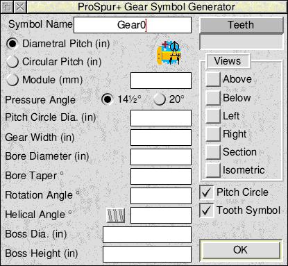
Figure 1.
The ultimate goal of ProSpur+ is to produce a ProCAD+ file containing gear symbols. These symbols must have names. The first writable icon in the dialogue box contains the symbol name. When the name ends with a number it will be incremented once the symbol file has been saved. (This feature may be turned off. See section 3.) The incrementing feature helps to avoid the duplication of symbol names, as ProCAD+ identifies symbols by their unique names.
Below the symbol name are three radio-type buttons that allow the selection of the way in which the data are to be interpreted. The writable icon opposite "Module" will contain the actual value.
The Diametral Pitch is probably the most common way of specifying a gear for British and American use. It is defined as the ratio of the number of teeth to the number of inches in the pitch circle diameter. When this option is selected the units for all other length measurement default to inch units.
The Circular Pitch is the distance along the circumference of the pitch circle between corresponding points on adjacent teeth. When this option is selected the units for all other length measurement default to inch units.
The Metric Module, or Module, as it has now come to be known, is the ratio of the pitch circle diameter in millimetres to the number of teeth. When this option is selected the units for all other length measurement default to millimetre units. The units shown in parentheses beside length measurements will also change to show this.
NOTE: When entering length data in writable icons the units shown in parentheses are the default units if none are specified with the data value. Alternatively, in or " or mm may be appended to the value to over-ride the default and specify the actual units intended (inches or millimetres only).
The pressure angle is fully described in the glossary. For most British and American practice an angle of either 14½° or 20° is used. (ProSpur+ can use other angles if needed. See section 3.)
The Pitch Circle Diameter specifies the diameter of the circle through the pitch point, having its centre at the axis of the gear. Pitch circles of meshing gears should touch tangentially.
This is the width or thickness of the gear. If no side views, sections or isometric views are required then this value may be left blank.
This is the diameter of the hole in the middle of the gear. If the hole is to be tapered then this diameter is measured at the front face unless a front boss is to be used, in which case this is the diameter at the outer edge of the boss. In other words, it is always the diameter at the front of the whole gear.
Leave this value empty or zero if no taper is required. If a tapered bore is required then enter a value in degrees or as a ratio eg: 1:10. A positive taper reduces the bore from front to back. A negative taper may be used to increase the bore from front to back. Tapers causing holes to close or bosses to be cut will display an error message.
The gear symbol is normally created so that the centre of a tooth is at the 0° position. The rotation angle permits the whole symbol to be defined rotated by this amount. This is not the same as rotating the symbol in ProCAD+ as the rotation is shown in all the projections for the additional views that ProSpur+ can provide.
This should be left at 0 unless a helical gear is required. The button to the left of the writable switches between right and left hand.
If no bosses are required, simply leave this entry empty. ProSpur+ can, however, provide for either one or two bosses. If a single value is entered here it is taken as the diameter of the front boss. A second value may be entered after a comma to denote the diameter of the second, back boss. If a back boss is required but no front boss then enter zero followed by a comma and then the second boss diameter.
As for the boss diameters the boss heights may be separated by a comma. Two boss diameters will require two boss heights.
The box marked Teeth is not used for data entry. It is for information. If the data has been entered for Diametral Pitch or its equivalent and the Pitch Circle Diameter then clicking on this box will cause the number of teeth to be shown, calculated from the entered values. The number of teeth is also updated when OK is clicked.
Normally ProSpur+ creates a symbol that shows the side of the gear that displays the profile of the teeth. Other views may be selected by turning on the following buttons by clicking on them.
This option provides an extra view as a symbol using the entered name, preceded by A_. The view is as from above the original view, using third angle projection. The tips of the teeth will be projected into the view and any bosses will be shown. The bore will be shown as a short-dash line.
This option provides an extra view as a symbol using the entered name, preceded by B_. The view is as from below the original view, using third angle projection. The tips of the teeth will be projected into the view and any bosses will be shown. The bore will be shown as a short-dash line.
This option provides an extra view as a symbol using the entered name, preceded by L_. The view is as from the left of the original view, using third angle projection. The tips of the teeth will be projected into the view and any bosses will be shown. The bore will be shown as a short-dash line.
This option provides an extra view as a symbol using the entered name, preceded by R_. The view is as from the right of the original view, using third angle projection. The tips of the teeth will be projected into the view and any bosses will be shown. The bore will be shown as a short-dash line.
This option provides a cross-section view as a symbol using the entered name, preceded by S_. The view is a cross-section cut through the gear including the bosses. The cut portions will be filled with standard hatching. (The hatching may be altered. See section 3.)
This option provides an isometric view as a symbol using the entered name, preceded by I_. The view is as from the front of the original view with the top tipped away from the viewer. All hidden detail will be removed. The second or back boss will not be shown.
This switch controls the drawing of the chain line circle that marks the pitch in the standard side view (and the equivalent ellipse in the isometric view). If the circle is not required simply turn this switch off.
Normally ProSpur+ creates the symbol for the standard view by repeating a tooth symbol, rotated around the pitch circle. The tooth symbol has the name entered preceded by T_ for its name. If, for any reason, it is necessary to change the appearance of the teeth then modifying this one tooth symbol will cause them all to change. Sometimes the standard symbol is easier to edit if its teeth are made up of lines instead of symbols. If this is required then turn the Tooth Symbol switch off. Isometric projections do not use tooth symbols as the projection of each tooth is different.
Before clicking on OK check that all the relevant values have been entered and that the directory view to receive the file is visible. Alternatively, it is possible to drop the file directly on to a ProCAD+ drawing in a ProCAD+ window. If the second option is chosen then it will be necessary to check that the symbol names have not already been used on the drawing by looking at the contents of the ProCAD+ symbol tool dialogue box.
When OK is clicked the data are checked and any errors will be reported. The number of teeth will be shown in the "Teeth" box. If no errors are detected then a "Save as" dialogue box will appear that will allow the newly created file of symbols to be saved.
Once the symbols have been created they may be used directly in ProCAD+ on any drawing. The gears are always created full size and so may need scaling to comply with certain drawings. This may be done by scaling the symbols using the symbol tool dialogue box or by using the Transform option on the ProCAD+ Select menu.
Only one isometric view is provided as the other two views may be obtained by rotating the same symbol through 120° and 240°.
If a symbol needs to be cut or edited then it should be converted to a group first. If tooth symbols are used then these will need to be converted to groups as well.
ProSpur+ is supplied ready to use but it may be customized by editing the file called Params inside the !ProSpur+ application. In order to get at this file hold the Shift key down while double clicking Select on the !ProSpur+ icon in the directory viewer. This will open the application's directory viewer and the Params file should be visible. Load this into !Edit and make what alterations are needed. Save the file when editing is complete and then re-load ProSpur+ on the icon-bar with the new parameters. Below is a list of all the parameters in alphabetical order, along with their meanings and default settings. The glossary in the next section may help with the explanation of some of the more unusual terms.
ABOVE 0
This is a 0 or 1 setting to indicate the initial state of the Above button in the View list.
ADDENDUM 1.0
The value entered here divided by the diametral pitch gives the addendum to be used.
BELOW 0
This is a 0 or 1 setting to indicate the initial state of the Below button in the View list.
CENTRE 1
This is a 0 or 1 setting to indicate whether a Point is to be used at the symbol centre.
DEDENDUM 1.25
The value entered here divided by the diametral pitch gives the dedendum to be used.
DASHEDBORE 1
This is a 0 or 1 setting to indicate whether the bore is to be shown in the Above, Below, Left and Right views as a dashed line (1) or omitted (0).
FILLANG 45
This is the angle in degrees for the hatching of cross-section views.
FILLETRAD 0.39
The value entered here divided by the diametral pitch gives the tooth fillet radius to be used. Zero can be entered if no fillet is required.
FILLGAP 0.25mm
This is the back-off distance for the hatching of cross-section views. This prevents the shading going outside the outline on pen plotters. For printing this may be reduced to zero.
FILLSIZE 3mm
This is the distance between the fill lines for the cross-hatching of section views.
INCNUM 1
This is a 0 or 1 setting to indicate whether numbers in symbol names should be incremented after a successful save.
ISOMETRIC 0
This is a 0 or 1 setting to indicate the initial state of the Isometric button in the View list.
LEFT 0
This is a 0 or 1 setting to indicate the initial state of the Left button in the View list.
MODE 0
Mode takes a value of 0, 1 or 2 to indicate Diametral Pitch, Circular Pitch or Module.
PITCHCIRCLE 1
This is a 0 or 1 setting to indicate the initial state of the Pitch Circle button below the View list.
PRESSANG 14.5
The Pressure Angle is usually set to 14.5 or 20 degrees but it may be set to a different angle which can be selected by turning off both of the "radio" buttons using the Adjust right mouse button.
RIGHT 0
This is a 0 or 1 setting to indicate the initial state of the Right button in the View list.
SECTION 0
This is a 0 or 1 setting to indicate the initial state of the Section button in the View list.
SYMNAME Gear0
This is the name that will initially appear in the main ProSpur+ dialogue box at start up.
TOOTH 0.5
This is the fraction of the space occupied by a tooth. Values of less than 0.5 imply backlash. (See glossary.)
TOOTHSYM 1
This is a 0 or 1 setting to indicate the initial state of the Tooth Symbol button below the View list.
This short glossary lists some of the terms used by gear manufacturers and users that are relevant to the use of ProSpur+. Terms that are relevant only to the generation of involute curves, as carried out internally by ProSpur+, are not included.
The Addendum is the radial or perpendicular distance between the pitch circle and the top of the tooth. (Fig. 2)
Figure 2.
Backlash is the shortest distance between non-driving teeth in mating gears. (Fig. 3)
Figure 3.
The Bore Diameter is the diameter of the hole in the gear (Fig. 4)
Figure 4.
The Boss Diameter is the outside diameter of the boss or hub that projects from the side of the gear. (Fig. 4)
The Boss Height is the amount that the boss or hub projects from the side of the gear. (Fig. 4)
This is the distance between the centres of two gears whose pitch circles just touch (Fig. 7)
The Circular Pitch is the distance along the circumference of the pitch circle between corresponding points on adjacent teeth. (Fig. 5)
Figure 5.
The Dedendum is the radial or perpendicular distance between the pitch circle and the bottom of the tooth space. (Fig. 6)
Figure 6.
The Diametral Pitch is the ratio of the number of teeth to the number of inches in the pitch circle diameter.
See tooth fillet.
The Gear Ratio is the ratio of the numbers of teeth in mating gears.
See Boss Diameter.
This is the name given to the geometric shape of the contact portion of the tooth face. (Fig. 9)
This is the line along which contact between mating teeth occurs. (Fig. 7)
Figure 7.
The Metric Module, often just known as Module, is the ratio of the pitch circle diameter in millimetres to the number of teeth.
The Pitch Circle is the circle through the pitch point having its centre at the axis of the gear. (Fig. 7)
The Pitch Point is the intersection between the line of centres and the line of action. (Fig. 7)
The pressure angle is the angle between the tangent to the tooth profile and a radial line perpendicular to the pitch circle. (Fig. 8)
Figure 8.
This is the radius of the circle at the bottom of the tooth space. (Fig. 9)
Figure 9.
This is the curved surface or fillet joining the side of the tooth to the bottom land at the root radius. (Fig. 9)
This section lists some of the more common error messages that can be produced by ProSpur+.
Bore too big.
The bore diameter value entered is greater than the root radius and would cut off the teeth.
Boss has no height value.
A boss diameter has been entered but no height.
Boss too big.
The boss diameter value entered is greater than the root radius and would project beyond the teeth.
Fewer than 3 teeth.
Self explanatory.
Gear must have width to use Views.
If any of the extra views are to be created a Gear Width value must be entered.
Insufficient memory. Please tidy up unwanted tasks and try again.
ProSpur+ has run out of memory.
No Diametral Pitch given.
A Diametral Pitch, Circular Pitch or Module value must be entered in order to create a gear.
No Pitch Circle Diameter given.
The Pitch Circle Diameter must be entered in order to create a gear.
No symbol name given.
A symbol name of up to 23 characters must be provided before a symbol can be created.
Taper error.
The requested taper either closes the hole or cuts a boss.
Too many teeth.
More than 100 teeth required.